OceanBase: A 707 Million tpmC Distributed Relational Database System
Goals of OceanBase
OceanBase has several key goals aimed at addressing the limitations of traditional RDBMS and enhancing database performance and usability. Here are the main goals:
-
Fast Scale-Out and Scale-In:
- OceanBase aims to achieve rapid scaling on commodity hardware, allowing businesses to expand or reduce their database resources quickly. This is crucial for maintaining high performance while keeping total cost of ownership (TCO) low, especially during business fluctuations like promotions
-
Cross-Region Deployment and Fault Tolerance:
- The system is designed to be fault-tolerant across different regions, ensuring that data integrity is maintained even if one region fails. This is a significant improvement over classical RDBMS, which often rely on hardware availability for high availability
-
Compatibility with Mainstream Classical RDBMS:
- OceanBase seeks to minimize the cost, time, and risk associated with migrating legacy applications from traditional RDBMS. By being compatible with widely used systems, it allows for easier transitions for organizations looking to upgrade their database solutions
-
Cost-Effectiveness:
- One of the primary goals is to provide a more cost-effective solution compared to classical RDBMS. OceanBase aims to reduce the financial burden associated with database management while still delivering high performance and reliability
-
High Availability:
- OceanBase is designed to ensure high availability of services, independent of hardware failures. This is achieved through its distributed architecture, which enhances resilience and uptime for critical applications
Oceanbase Infrastructure
- Distributed Architecture
- OceanBase adopts a distributed shared-nothing architecture, where each node (server) is independent, with no shared disk or memory between them.
- It is composed of multiple clusters, where each cluster can scale horizontally by adding more nodes.
- Separation of Storage and Compute
- Storage Layer: Data is stored in distributed storage, where the data is sharded and replicated across multiple nodes. It uses distributed file systems to store data blocks.
- Compute Layer: Query processing and computation are done by compute nodes, which can be independently scaled based on demand.
- Fault Tolerance and High Availability
- OceanBase employs replication for fault tolerance, ensuring that multiple copies of data exist across different nodes or data centers.
- In case of node failure, data is still accessible from other replicas without downtime.
- Automatic Failover: If a primary node fails, the system can automatically switch to a secondary node.
- Distributed Transactions (ACID Compliance)
- It supports distributed transactions and ensures ACID (Atomicity, Consistency, Isolation, Durability) properties across distributed nodes.
- Two-Phase Commit (2PC) protocol is used to ensure the consistency of transactions across multiple nodes.
-
Sharding and Data Distribution OceanBase uses automatic sharding to divide data into smaller, more manageable pieces (shards) and distribute them across different nodes. The sharding is designed to minimize cross-node communication to optimize performance.
-
Global Consistency
- It guarantees global consistency using a distributed consensus protocol (like Paxos or Raft), ensuring that all replicas of a piece of data are in sync.
- SQL Support and Compatibility
- OceanBase supports standard SQL, making it compatible with traditional RDBMS systems, allowing seamless migration from other SQL databases.
- It supports multi-model databases, enabling the use of relational, key-value, and document models within the same system.
-
Elastic Scalability OceanBase provides elastic scaling, where you can scale compute or storage resources independently, both horizontally (adding more nodes) and vertically (adding more resources to existing nodes).
-
Multi-Datacenter Deployment It supports multi-datacenter deployment, allowing replication and data distribution across geographically separated data centers for disaster recovery and latency optimization.
-
Performance Optimizations It includes optimizations for high throughput and low-latency operations, including advanced indexing, query optimization, and in-memory processing for faster query execution.
-
Online Maintenance and Upgrades OceanBase allows online maintenance, meaning that it can perform upgrades and maintenance tasks without affecting system availability or performance.
-
Distributed Storage Engine OceanBase uses a custom storage engine that provides strong consistency and high performance for both OLTP (Online Transaction Processing) and OLAP (Online Analytical Processing) workloads.
-
Integrated Monitoring and Management It includes built-in monitoring tools for real-time performance tracking, resource utilization, and fault detection. Management interfaces provide administrators with tools to handle system configuration, data management, and resource allocation.
-
Security Features OceanBase includes security features such as encryption (at rest and in transit), access control, and auditing to ensure data protection and compliance with industry standards.
-
Cloud-Native OceanBase is designed to be cloud-native, optimized for deployment on cloud platforms, and integrates well with containerized environments (such as Kubernetes) for dynamic scaling and orchestration.
-
Deployment Flexibility It can be deployed both in on-premises data centers or in the cloud, supporting hybrid cloud environments.
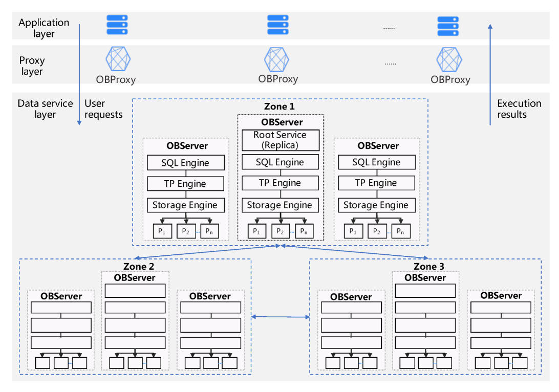
System Architecture of Oceanbase
-
Application Layer: This is the topmost layer where user applications initiate SQL requests. The application layer is responsible for sending these requests to the system, which are typically generated by user interactions or automated processes. It serves as the interface between the end-users and the database system, ensuring that user commands are properly formatted and transmitted.
-
Proxy Layer (OBProxy): The Proxy Layer acts as an intermediary between the Application Layer and the Data Service Layer. When a request is received from the application, the OBProxy routes it to the appropriate database node (OBServer) based on the request type and the current load on the servers. This routing is essential for balancing the load across the database nodes and optimizing performance. The proxy layer also handles aspects like connection management and request forwarding, ensuring that the application remains unaware of the underlying complexities of the database architecture
-
Data Service Layer (OBServer): The Data Service Layer is where the actual data processing occurs. Each OBServer is responsible for executing the SQL requests routed to it by the Proxy Layer. This layer interacts with the database tables, which are partitioned for efficient data management and load balancing. Each partition has replicas in different zones, forming a Paxos group to ensure data reliability and availability. The execution results are then sent back through the Proxy Layer to the Application Layer, completing the request-response cycle
SQL Engine
Example Query: SELECT name, age FROM users WHERE age > 30;
- Parser
- Input: The SQL query string "SELECT name, age FROM users WHERE age > 30;".
- Process: The Parser breaks the query into tokens (e.g., SELECT, name, age, FROM, users, WHERE, age > 30) and checks the syntax.
- Output: The query is parsed into an abstract syntax tree (AST), representing the structure of the SQL statement.
- Resolver
- Input: The tokens from the Parser.
- Process: The Resolver translates these tokens into actual database objects based on the schema (e.g., users is a table, name and age are columns).
- Output: The Resolver generates a statement tree representing the query's relationships, such as SELECT from users where age > 30.
- Transformer
- Input: The statement tree from the Resolver.
- Process: The Transformer analyzes the semantics of the query and may rewrite it if necessary. For example, it might choose a more efficient way to filter age > 30 (like using an index if available).
- Output: The SQL query is transformed into an equivalent form that will be more efficient to execute, while still logically the same.
- Optimizer
- Input: The transformed SQL query.
- Process: The Optimizer evaluates multiple execution plans and selects the most efficient one. It may decide to use an index scan for the age column or a table scan if no index is available.
- Output: The Optimizer produces the best execution plan (e.g., use index scan for age if available).
- Code Generator
- Input: The optimized execution plan from the Optimizer.
- Process: The Code Generator converts the optimized plan into executable code that the database engine can run (e.g., specific machine code or database engine instructions for scanning the users table).
- Output: The executable SQL execution code, ready for execution.
- Executor
- Input: The executable SQL code from the Code Generator.
- Process: If this is a local execution plan, the Executor fetches the required rows from the users table, applies the WHERE age > 30 filter, and returns the name and age columns. If it's a distributed execution plan (e.g., users is sharded across nodes), the Executor splits the query into smaller tasks (e.g., fetching data from multiple shards), distributes them to the relevant nodes using RPC, and then aggregates the results.
- Output: The results are returned to the user, e.g., a list of names and ages of users over 30.
Summary of Execution Flow:
- Parser: Tokenizes and structures the query.
- Resolver: Resolves tokens to schema objects (tables, columns).
- Transformer: Rewrites the query to an optimized form.
- Optimizer: Chooses the best execution plan (e.g., using indexes).
- Code Generator: Translates the plan into executable code.
- Executor: Executes the query, either locally or in a distributed manner, and returns the results.
LSM Tree Based Architecture
-
Log-Structured Merge-tree (LSM-tree): OceanBase utilizes an LSM-tree architecture, which is designed to optimize write operations. This architecture is similar to that used in systems like Bigtable, allowing for efficient data handling and storage management
-
Data Organization: The data in OceanBase is divided into two main components:
- Static Baseline Data: This data is stored in a read-only format known as SSTable (Sorted String Table). Once generated, SSTables are not modified.
- Dynamic Incremental Data: This data is stored in MemTable, which supports both reading and writing. DML (Data Manipulation Language) operations such as inserts, updates, and deletes are first written to MemTable
-
Data Flushing: When the MemTable reaches a predefined size, it is flushed to disk and converted into SSTable. This process helps in managing memory usage and maintaining performance during high write loads
-
Query Processing: During query execution, OceanBase queries both SSTable and MemTable separately. The results from these two sources are then merged to provide a unified response to the SQL layer. This dual querying mechanism is crucial for maintaining data consistency and performance
-
Caching Mechanisms: To enhance performance, OceanBase implements both Block Cache and Row Cache in memory. These caches reduce the need for random reads from the baseline data, significantly speeding up query responses, especially for single-row queries
-
Compaction Processes: OceanBase performs two types of compaction:
- Minor Compaction: This occurs when the incremental data in MemTable reaches a certain scale, converting it into SSTable.
- Major Compaction: A daily process that merges mutations and produces a new version of the baseline data, ensuring that the system remains efficient and up-to-date
-
Optimizations for Small Queries: OceanBase has implemented various optimizations for small queries, which are common in OLTP (Online Transaction Processing) operations. These optimizations allow OceanBase to achieve performance levels comparable to in-memory databases, making it highly efficient for transactional workloads
In summary, the LSM-tree based architecture of OceanBase is designed to efficiently manage data storage and retrieval, ensuring high performance and scalability in a distributed relational database environment.
OceanBase's compaction mechanism
Key Concepts:
-
Macroblocks:
- OceanBase divides data into units called macroblocks, each with a size of 2MB. This segmentation allows for more efficient management and compaction of data.
-
Major Compaction:
- A major compaction occurs periodically and is a process where the system reorganizes and rewrites the data.
- If data modifications (inserts, updates, deletes) occur within a macroblock, the system rewrites the macroblock during the major compaction.
- If no modifications are made to a macroblock, it is reused in the new baseline data, meaning no additional I/O cost is incurred.
- This method of handling data during compaction reduces the overall cost of major compactions compared to other systems, such as LevelDB or RocksDB, which often require more extensive data rewriting during compaction.
Incremental Major Compaction:
- OceanBase uses daily incremental major compaction. This means that only the modified macroblocks (those that were changed by insertions, updates, or deletions) need to be rewritten during each daily compaction cycle.
- This minimizes the impact on system performance during compaction by targeting only the affected data blocks rather than rewriting all blocks.
Staggered Compaction with Round-Robin Mechanism:
- To avoid interrupting normal user operations during compaction, OceanBase employs a round-robin compaction mechanism.
- This staggering of compaction operations ensures that they occur in small batches and are spread across time, thereby isolating compaction from normal user requests.
- This round-robin mechanism improves overall system performance by reducing interference from compaction processes.
Off-Peak Scheduling for Major Compaction:
- Major compaction is typically scheduled during off-peak hours when there is more available CPU and memory capacity.
- During this time, OceanBase can use more aggressive compression algorithms that provide better data compression without harming system performance.
- Since the compaction is incremental (only modified macroblocks are rewritten), the overall I/O cost is low.
Schema Modifications:
- When the schema of a table is modified (e.g., adding a column or changing a column's attributes), it is treated as a metadata operation rather than a data operation.
- For example, when a new column is added, data in the new column is gradually filled in the background through a process called progressive merge. This means that the system does not have to rewrite all the data at once.
- To minimize the impact of this operation on the business, the filling process can be gradual, such as filling 10% per day. This ensures that the system continues to operate efficiently while the new data is incorporated.
Minor Compaction:
- A minor compaction is a different process. It focuses on compacting in-memory mutations, specifically the MemTable, and writes this data to disk. This operation also frees up the memory occupied by the MemTable.
- Multiple minor compactions can be merged into a larger compaction operation.
Baseline
The baseline is the initial, unmodified version of the data in a partition or table. It represents the snapshot of data at a given point in time.
Mutation Increment
Mutation increment refers to changes made to the data after the baseline is created. These changes include insertions, updates, and deletions.
Redo Log
The redo log is a write-ahead log (WAL) that stores all changes made to the database (mutations) before they are applied to the actual data storage (i.e., the baseline).
OceanBase Replica Types:
-
Full Replica:
- Contains: Baseline, Mutation Increment, and Redo Log.
- A complete replica of a partition or table.
-
Data Replica:
- Contains: Baseline and Redo Log.
- Copies minor compactions from a full replica on demand.
- Can be upgraded to a Full Replica after replaying redo logs.
- Reduces CPU and memory by eliminating redo log replay and MemTable.
-
Log Replica:
- Contains: Redo Log only.
- Part of the Paxos group for high availability.
- No MemTable or SSTable.
- Reduces storage and memory cost, while maintaining high availability with two full replicas and one log replica.
Traditional Two-Phase Commit (2PC) Protocol:
2PC is a protocol used to ensure atomicity in distributed transactions, where the system must guarantee that all parts of the transaction either commit or roll back as a whole. Here’s how the 2PC protocol typically works:
- Transaction Example: Distributed Money Transfer
- Participants: Two nodes, Node A (handles account UA) and Node B (handles account UB).
- Process: When a user initiates a transfer (e.g., moving money from UA to UB), both nodes need to check if:
- UA has enough balance and is not subject to any limits.
- UB is eligible to receive money (not frozen).
- If both checks pass:
- The system locks the accounts UA and UB to prevent other operations during the transfer.
- This is followed by the Two-Phase Commit protocol.
- Two-Phase Commit Process:
- Prepare Phase:
- Each node (Node A and Node B) generates redo logs to persist the decision (commit or abort).
- The system prepares the transaction and ensures data is in a consistent state.
- Commit Phase:
- If both nodes successfully prepare their operations (i.e., the checks pass), they are instructed to commit:
- Node A deducts from UA.
- Node B adds to UB.
- If any failure occurs at this stage (e.g., Node A or Node B fails), the transaction is rolled back (aborted).
- If both nodes successfully prepare their operations (i.e., the checks pass), they are instructed to commit:
- Prepare Phase:
Problems in Traditional 2PC in Distributed Systems:
In a shared-nothing system, if one node fails during the transaction:
- Uncertainty: If Node A fails, the status of its operation on UA is uncertain:
- The Prepare phase might be incomplete, or it could have succeeded or failed.
- If Node A fails permanently or takes time to recover, the status of the transaction remains uncertain, causing the distributed transaction to be in a partially committed state.
- Communication Failures: Even monitoring nodes might not reliably determine the state of a failed node because of communication issues.
OceanBase's Solution: Paxos for Fault Tolerance in 2PC
OceanBase introduces the Paxos protocol to enhance 2PC with automatic fault tolerance and reliable distributed transactions. Here’s how it works:
- Paxos Protocol Overview:
- Paxos is a distributed consensus protocol that allows multiple nodes to agree on a single value, even if some nodes fail.
- It is used to ensure consistency in a distributed system, even in the face of node failures.
- In OceanBase, Paxos ensures that all participant nodes (involved in a distributed transaction) are kept in sync and can recover in the event of a failure.
- Fault-Tolerant Distributed Transactions:
- OceanBase leverages Paxos to replicate the state of each transaction across multiple copies of each participant node.
- If a node (e.g., Node A) fails, Paxos allows the system to elect a new replica to continue providing services and recover the state of the original node.
- This guarantees that the distributed transaction can continue and complete even if one node fails, thus reducing the uncertainty and risk of data inconsistency.
Optimizations in OceanBase’s 2PC Protocol:
OceanBase improves the traditional 2PC protocol by optimizing both the participant and coordinator roles, reducing the number of Paxos synchronizations needed, which ultimately enhances transaction performance and reduces latency.
- Traditional 2PC vs. OceanBase Optimized 2PC:
- Traditional 2PC typically requires 4 Paxos synchronizations: one for the prepare phase and one for the commit phase, as well as two more for the participant replicas.
- OceanBase reduces the synchronizations to 3 Paxos synchronizations, which improves efficiency:
- The coordinator logs the transaction state before processing, and the prepare and commit steps are optimized.
- This means fewer steps are needed to reach consensus, reducing the overall latency.
- Further Optimization (2 vs. 3 Paxos):
- OceanBase takes this even further by optimizing the coordinator’s role:
- The first participant in the distributed transaction is chosen as the coordinator for the 2PC process.
- In the case of disaster recovery or node failure, the coordinator dynamically reconstructs the transaction state by collecting the local states of all participants.
- This results in only 2 Paxos synchronizations instead of 3, reducing transaction latency significantly.
- OceanBase takes this even further by optimizing the coordinator’s role:
- Read Optimization:
- OceanBase offers an option to enable read optimization, which can reduce transaction time further by using caching mechanisms.
- However, enabling read optimization may add an extra network round-trip for certain transactions, which is a trade-off between speed and reliability.
- Transaction Logging:
- In OceanBase’s 2PC implementation, all prepare logs of a transaction are persisted on a majority of the Paxos group before any further operations are executed.
- This ensures that in the event of a failure, the transaction can still be completed as long as the majority of participants have completed the prepare phase.